Vietnam Mountain Road Rock Breaking Project Conditions
The largest rock had a natural free face on one side, while the other side connected to the mountain. Before drilling, Mr. Nguyen checked the excavator position and planned the rock removal direction. He then set the drilling area according to the exposed rock height, existing cracks, and road width.
The team focused on three points:
- The rock stood about 1.2 m from the road edge.
- The excavator needed a stable working position.
- The team planned to move the split rock toward the outside of the road.
Excavator Hydraulic Rock Splitter Configuration
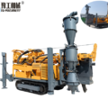
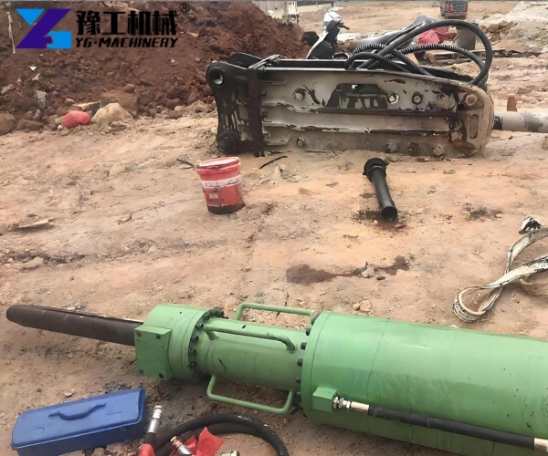
The equipment included a Rock Drilling Machine and a Splitting Machine. In addition, the system required an excavator of at least 25 t.
| Item | Parameter |
| Rock Drilling Machine Power | 24 kW |
| Drilling Hole Diameter | 120 mm |
| Maximum Drilling Depth | 1600 mm |
| Drilling Speed | 1 m/min |
| Splitting Depth | 1000 mm |
| Manufacturer Rated Splitting Force | 8000 T* |
| Rotation Angle | 120° |
| Maximum Propulsion | 25 kN |
| Maximum Pullout Force | 70 kN |
| Excavator Requirement | ≥25 t |
8000 T is the rated value in the available manufacturer parameter data. The actual working pressure, cylinder diameter, and test conditions should be confirmed with the technical data for the specific equipment model. It is not treated as the actual output force recorded at this site.
Drilling Layout for Mountain Road Rock Breaking
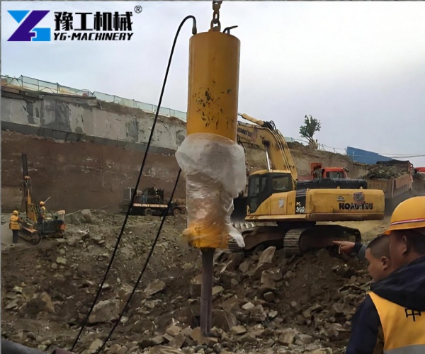
First, the team drilled six holes in the largest rock. The initial hole spacing measured about 400 mm, while the row spacing measured about 350 mm. The team drilled each hole to about 1.2 m and inclined the drilling direction about 5° toward the free face.
The equipment can drill to a maximum depth of 1600 mm. However, the team did not use the full depth at this site. Instead, they selected a 1.2 m hole depth according to the rock height, splitter insertion depth, and planned crack direction.
Hard Layer Adjustment During Drilling
Initially, the drilling speed stayed close to 1 m/min. However, the drill reached a harder layer at the fourth hole, causing the speed to drop to about 0.5 m/min. The workers then checked the rock surface and moved the fifth hole about 80 mm toward the existing crack before continuing.
Hydraulic Rock Splitting Process
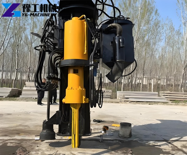
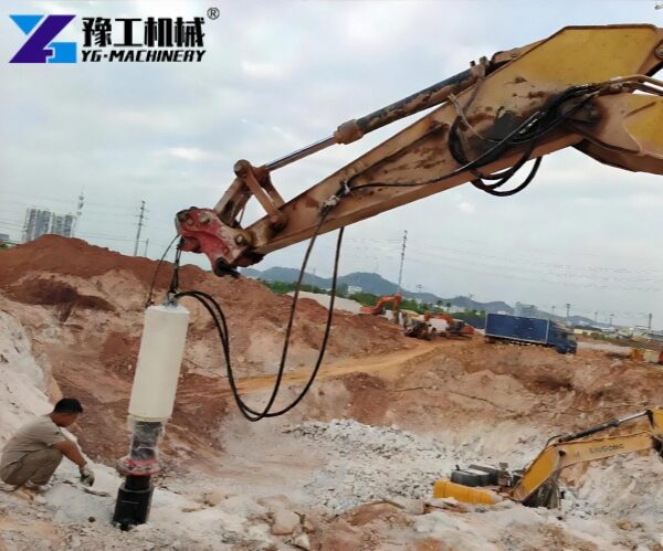
After drilling the 120 mm holes, the workers cleaned and checked each hole. Next, they positioned the Splitting Machine at the required hole locations. They inserted the splitter about 1.0 m and adjusted its angle according to the planned crack direction.
The team pressurized the first hole for about 35 seconds, and a crack then appeared. They split the second and third holes in sequence, allowing the crack to extend toward the free face. As the crack developed, the rock started to separate.
When the crack did not fully pass through the rock, the workers used secondary splitting according to the actual crack position. Therefore, they could make better use of the existing holes before adding new drilling positions.
Rock Removal and Safety Control
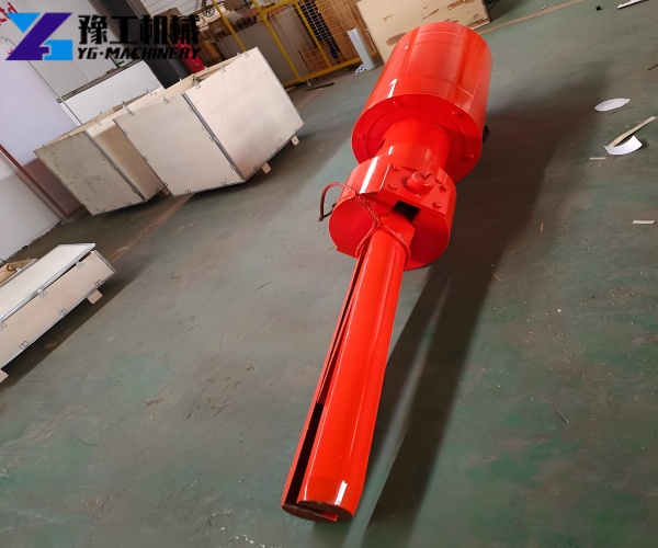
The first rock produced four separate pieces after splitting. The largest piece measured about 0.9 m × 0.7 m × 0.5 m. After splitting, the 25 t excavator moved the pieces toward the outside of the road. The team then repositioned the equipment for the other two rocks.
Meanwhile, the excavator remained on a stable surface during work on the mountain road. The workers kept hydraulic hoses away from the tracks and sharp rock surfaces. In addition, non-working personnel stayed outside the equipment working area during drilling and pressurization.
Near the road edge, the workers checked the slope condition and the possible movement direction of the rock before starting work. They also considered these conditions when selecting the splitting direction and excavator position.
Vietnam Project Results
The team completed the drilling, splitting, and removal of all three rocks. Before splitting, the largest rock measured about 3.2 m × 2.0 m × 1.5 m. After the operation, it produced four pieces, with the largest separated piece measuring about 0.9 m × 0.7 m × 0.5 m.
During drilling, the fourth hole reached a harder layer. As a result, the team reduced the drilling speed and adjusted the next hole position. The workers therefore adapted the drilling and splitting process to the actual rock conditions instead of using the same hole arrangement at every position.
The results also show why hydraulic rock splitter for excavator parameters need to match the rock conditions. The team used a 120 mm hole diameter and drilled to about 1.2 m, which remained below the equipment’s 1600 mm maximum drilling depth. Meanwhile, the 1000 mm splitting depth matched the splitter insertion depth used at the site.
YG Machinery Excavator Hydraulic Rock Splitter Configuration
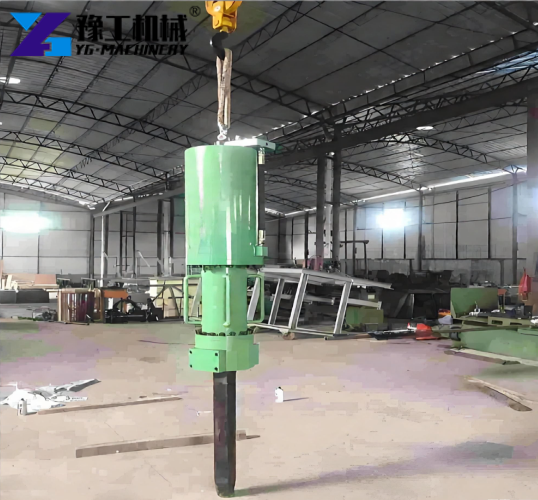
YG Machinery can configure the equipment according to rock size, drilling depth, free face, and excavator capacity. When purchasing an Excavator Hydraulic Rock Splitter, customers can provide the rock dimensions, required hole depth, site conditions, and excavator specifications.
For mountain road rock breaking, customers can also provide site photos, road width, the distance between the rock and road edge, and existing excavator information. These details help determine the drilling diameter, drilling depth, splitting setup, and excavator requirements.
Based on the available site information, the appropriate equipment configuration and quotation can then be provided.