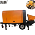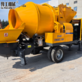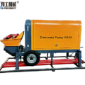
In May 2026, a residential construction project in Medellín, Colombia, entered the main concrete pouring stage. The customer, Carlos Rodríguez, needed to mix concrete at the site and pump it to different pouring locations inside the building.
The main pouring section reached about 35 m, with a horizontal delivery distance of around 120 m. The project used C30 concrete with a slump of about 160 mm. Limited working space also made manual concrete transfer difficult.
Project Requirements in Medellín
Project type: Residential building construction
Concrete grade: C30
Concrete slump: About 160 mm
Vertical delivery height: About 35 m
Horizontal delivery distance: About 120 m
Site voltage: 380 V
Aggregate: Within the machine specification
Main requirement: On-site mixing and continuous pumping
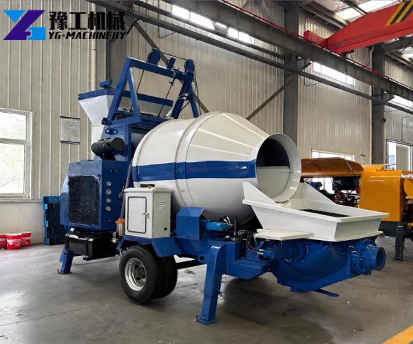
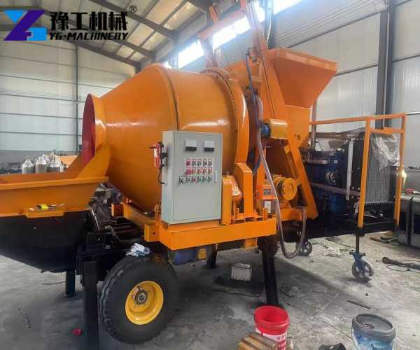
Based on these conditions, YG selected a Concrete Mixer Pump with a 40 m³/h theoretical concrete output, 45 kW pumping motor, 8 kW mixing motor, and φ200 × 800 mm concrete cylinder.
Concrete Mixer Pump Specifications
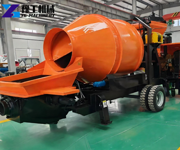
| Technical Parameter | Selected Value |
| Theoretical Mixing Capacity | 15 m³/h |
| Theoretical Concrete Output | 40 m³/h |
| Maximum Delivery Distance | 50 m vertical / 200 m horizontal |
| Distribution Valve | S-tube valve |
| Hopper Volume | 600 L |
| Pumping Motor Power | 45 kW |
| Mixing Motor Power | 8 kW |
| Concrete Delivery Pressure | 6 MPa |
| Concrete Cylinder | φ200 × 800 mm |
| Maximum Aggregate Size | 40 mm grit / 30 mm gravel |
| Voltage | 380 V |
| Weight | 3500 kg |
| Dimensions | 4200 × 2100 × 3300 mm |
Mixing Capacity and Pumping Output
The selected machine provides a theoretical mixing capacity of 15 m³/h and a theoretical pumping output of 40 m³/h. These figures describe different operations and do not represent the actual output during every construction stage.
During the main 6-hour pumping operation, the project placed about 72 m³ of concrete, giving an average actual delivery rate of about 12 m³/h. The remaining concrete volume for the 180 m³ construction stage was completed during later pouring operations.
Concrete Mix and S-Tube Valve
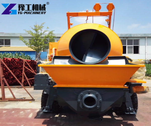
The project used C30 concrete with a slump of about 160 mm. Aggregate size stayed within the equipment specification, with up to 40 mm grit and 30 mm gravel.
The S-tube valve controlled concrete discharge from the hopper into the delivery pipeline. The machine has a maximum stated concrete delivery pressure of 6 MPa.
How the Concrete Mixer Pump Was Used on Site
The concrete delivery process followed this sequence:
Material preparation → Concrete mixing → Hopper feeding → S-tube valve pumping → Pipeline delivery → Concrete pouring
Cement, sand, aggregate, and water were prepared near the machine. After mixing, the concrete entered the 600 L hopper and moved through the S-tube valve into the delivery pipeline.
This setup connected concrete preparation with concrete placement and reduced repeated manual transfer around the building.
Pipeline Layout and Site Adjustments
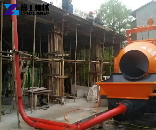
The project used approximately 155 m of 125 mm concrete delivery pipe, including about 120 m of horizontal pipe and a 35 m vertical section. The route contained six 90-degree bends.
For pipeline planning, each 90-degree bend added an estimated 6 m of equivalent straight-pipe length. The six bends therefore added about 36 m, giving an estimated straight-pipe equivalent of about 191 m for the 155 m pipe route.
The vertical lift required separate consideration and did not simply count as horizontal pipe length. The planned 35 m vertical lift remained below the machine’s 50 m theoretical vertical delivery limit, while the calculated straight-pipe equivalent remained below the stated 200 m theoretical horizontal delivery figure.
The installation also followed several controls:
- The machine stayed close to the material preparation area.
- Unnecessary bends were avoided.
- The vertical pipe section was fixed to the building structure.
- Pipe joints and clamps were checked before pumping.
- Workers monitored concrete flow and pressure during operation.
Site Issues and Pumping Control
The main focus was maintaining stable concrete flow through the long pipeline.
Concrete consistency: The C30 concrete had a target slump of about 160 mm. Workers checked the mix before pumping to maintain suitable flow.
Aggregate size: Aggregate remained within the specified size range to reduce the risk of pipeline blockage.
Power supply: The site provided 380 V, matching the selected machine configuration.
Pumping pressure: The actual operating pressure remained around 4.5 MPa during the main pumping operation, below the machine’s stated maximum of 6 MPa.
Pipeline condition: Workers checked joints, clamps, bends, and vertical fixing before pumping. No pipeline blockage occurred during the main 6-hour pumping operation.
Project Results
During the main 6-hour pumping operation, the project placed approximately 72 m³ of C30 concrete. The complete construction stage required about 180 m³, with the remaining volume completed during later pouring stages.
The main operation used a three-person crew:
- One worker prepared materials.
- One worker operated and monitored the pump.
- One worker handled concrete placement.
The actual pumping rate averaged about 12 m³/h during the six-hour operation. Material feeding, mixing cycles, pipeline resistance, and pouring intervals affected the actual rate.
The combined mixing and pumping process reduced manual concrete transfer and provided a direct connection between concrete preparation and placement.
Customer Feedback
Carlos Rodríguez said:
“The main requirement was to reduce manual concrete transfer and keep mixing and pumping connected. The Concrete Mixer Pump made it easier to organize the concrete work around the building.”
Concrete Mixer Pump for Similar Projects in Colombia
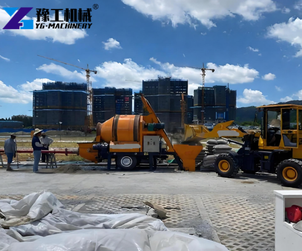
For similar construction projects, the equipment configuration should consider:
- Required concrete output
- Concrete grade and slump
- Vertical delivery height
- Horizontal delivery distance
- Pipe diameter and total pipeline length
- Number of bends
- Aggregate size
- Site voltage
- Available working space
These details help determine the pumping capacity, motor configuration, cylinder size, and pipeline arrangement.
Get a Concrete Mixer Pump Configuration from YG
Send YG the required concrete output, concrete grade and slump, vertical height, horizontal distance, pipe diameter, pipeline bends, aggregate size, site voltage, and project location.
YG can use these conditions to confirm a suitable Concrete Mixer Pump configuration for the construction project.